×
- Hello
- Login or Register
- Quick Links
- Live Chat
- Track Order
- Parts Availability
- RMA
- Help Center
- Contact Us
- Shop for
- Volkswagen Parts
My Garage
My Account
Cart
Genuine Volkswagen GTI Intake Manifold
Engine Intake Manifold- Select Vehicle by Model
- Select Vehicle by VIN
Select Vehicle by Model
orMake
Model
Year
Select Vehicle by VIN
For the most accurate results, select vehicle by your VIN (Vehicle Identification Number).
3 Intake Manifolds found

Volkswagen GTI Intake Manifold Part Number: 06L-133-201-FR
$176.42 MSRP: $247.08You Save: $70.66 (29%)Ships in 1-2 Business Days
Volkswagen GTI Intake Manifold Part Number: 06J-133-201-BH
$365.99 MSRP: $499.98You Save: $133.99 (27%)Ships in 1-2 Business Days
Volkswagen GTI Intake Manifold Part Number: 06L-133-201-ES
$731.99 MSRP: $923.06You Save: $191.07 (21%)Ships in 1-2 Business Days
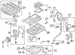
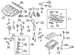
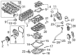
Volkswagen GTI Intake Manifold
The Intake Manifold of the Volkswagen GTI directs fresh charge air so that every cylinder gets an equal, high-speed supply, a design that has a direct effect on increasing throttle response and increasing overall engine thrust. The early Volkswagen hot hatches had cast aluminum or iron Intake Manifold designs which, though robust, were heavy, and later Volkswagen models were equipped with lighter composite plastic that reduces weight and keeps the air cooler to allow denser combustion. Over the years the responsibility of the manifold remained the same, but the fueling arrangements changed, with the carbureted and throttle body systems allowing the air to mix with the fuel in the runners; multiport injection systems introduced a nozzle at each end of the runners, and current direct injection GTI engines allow the manifold to pump only clean air into the chamber as the fuel now sprays directly into the chamber. No matter which period it was fueled in, the length of the runners and the internal volume were shaped in the manner of a harness to utilize the Helmholtz resonance to squeeze a minor pressure wave into the cylinders, providing additional torque. Recent models fit variable-length passages which are made shorter at high rpm and longer at low revs to give the engine a second manifold in one, effectively. The upper and lower halves and cylinder head port gaskets should be airtight as any leak distorts the air-fuel ratio and leads to unsmooth idling. The Intake Manifold may also have coolant passages containing temperature sensors that will provide the computer with essential information. Due to these combined characteristics, the new Volkswagen performance hatch will retain its rogue personality but will reach more stringent efficiency targets.
Choose OEM Intake Manifold for superior quality and long-lasting durability. They match the Volkswagen's factory specifications exactly and pass strict quality control. If you plan to replace Intake Manifold on your GTI, put OEM at the top of your list. You'll get the right fit, reliable performance, and peace of mind. We stock an extensive inventory of genuine Volkswagen GTI parts. It is easy to find what you need. You will love our competitive prices that help you save. No more hassle with returns or guesswork. Every part includes a warranty straight from the manufacturer. Get trusted quality, strong durability, and real value today.
Volkswagen GTI Intake Manifold Parts and Q&A
- Q: What precautions should be taken when disconnecting the battery and removing the intake manifold for 4-cylinder engines on Volkswagen GTI?A:If the battery is disconnected, several systems must be re-learned before they will work properly. Begin by relieving the fuel system pressure. Disconnect the cable from the negative battery terminal. Working from above in the engine compartment, remove the engine cover or air filter housing. For 1.4L (CZTA, DGXA) models, raise the vehicle and support it securely on jackstands, then remove the engine splash shield fasteners and shield. Drain the coolant and disconnect the EVAP canister hoses to the intake manifold. Remove the throttle body and disconnect the quick-connect fitting for the vacuum hose and the coolant hose to the intake manifold, then remove the hoses. Disconnect the coolant hoses from the intake manifold and the coolant hose under the intake manifold, removing the pipe fastener. Disconnect the electrical connectors from the fuel pressure sensor, the oil pressure switch, and the canister purge regulator. Remove the intake manifold bolts and the intake manifold, and if necessary, remove the fuel supply line to the fuel pump and plug the line. For installation, use new manifold gaskets, install the intake manifold, and tighten the bolts in sequence to the specified torque, with the remainder of installation being the reverse of removal. For 2.0L (CBPA) models, disconnect the fuel supply line and cover the openings to prevent debris from entering the fuel system. Clamp off the coolant hoses leading to the throttle body and remove them. Disconnect the electrical connectors from the fuel injectors, CMP sensor, and the EVAP canister purge valve. Unclip the wiring harness and EVAP hose clamp from the intake manifold, then open the locking ring and remove the EVAP canister purge valve. Remove the oil dipstick tube-to-engine block retaining fastener and rotate the tube out of the way. The intake manifold is secured with eight bolts; unscrew them and pull the intake manifold away from the engine at a slight angle for clearance. For installation, use new manifold gaskets, install the intake manifold, and tighten the bolts in several stages, working from the center out to the specified torque, with the remainder of installation being the reverse of removal. For 1.8L and 2.0L timing chain models, if the intake manifold is removed or replaced, the intake manifold runner position sensor must be adapted or relearned to the engine control module. Raise the vehicle and support it securely on jackstands, then remove the engine lower splash shield. On 1.8L and 2.0L models, remove the cooling fan shroud. Remove the coolant tube bracket bolt and separate the tube from the end of the intake manifold. Remove the charge air cooler inlet and outlet pipes. Disconnect the electrical connectors for the cooling system under the intake manifold and disconnect the fuel supply line, then disconnect the electrical connectors from the sensors on the intake manifold. On specific models, remove the engine oil filter and the throttle body. Disconnect the vacuum pump quick-connector and the manifold runner control valve from the lower rear side of the intake manifold. Disconnect the fuel line from the high-pressure fuel pump and from the pump to the fuel rail. Remove the intake manifold support bracket bolts and disconnect the electrical connector from the intake manifold runner position sensor and the camshaft position sensors. Remove the intake manifold mounting nuts and bolts, then pull the intake manifold back from the cylinder head to access the electrical harness bracket under the manifold. Remove the harness bracket fasteners and the harnesses from the intake manifold. Remove the intake manifold from the vehicle and cover all openings. On specific models, remove the fuel rail and replace the injector seals, then reinstall the fuel rail and injectors to the intake manifold. For installation, ensure the gasket is seated around the four ports of the intake manifold using new manifold gaskets, then install the intake manifold. Install the harness bracket and fasteners on the bottom of the intake manifold, then tighten the fasteners securely. Tighten the bolts in several stages, working from the center out to the specified torque, with the remainder of installation being the reverse of removal.

Related Volkswagen GTI Parts
 Volkswagen GTI Axle Shaft
 Volkswagen GTI Axle Support Bushings
 Volkswagen GTI Belt Tensioner
 Volkswagen GTI Brake Tubing Clips
 Volkswagen GTI Cylinder Head
 Volkswagen GTI Mass Air Flow Sensor
 Volkswagen GTI Mirror Switch
 Volkswagen GTI Oil Cooler Hose
 Volkswagen GTI Oil Filter Housing
Browse by Year
2024 Intake Manifold 2023 Intake Manifold 2022 Intake Manifold 2021 Intake Manifold 2020 Intake Manifold 2019 Intake Manifold 2018 Intake Manifold 2017 Intake Manifold 2016 Intake Manifold 2015 Intake Manifold 2014 Intake Manifold 2013 Intake Manifold 2012 Intake Manifold 2011 Intake Manifold 2010 Intake Manifold 2009 Intake Manifold 2008 Intake Manifold