×
- Hello
- Login or Register
- Quick Links
- Live Chat
- Track Order
- Parts Availability
- RMA
- Help Center
- Contact Us
- Shop for
- Volkswagen Parts
My Garage
My Account
Cart
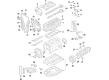
Genuine Volkswagen Golf R Camshaft
Cam- Select Vehicle by Model
- Select Vehicle by VIN
Select Vehicle by Model
orMake
Model
Year
Select Vehicle by VIN
For the most accurate results, select vehicle by your VIN (Vehicle Identification Number).
5 Camshafts found

Volkswagen Golf R Camshaft Part Number: 06K-109-022-S
$292.07 MSRP: $399.00You Save: $106.93 (27%)Ships in 1-2 Business Days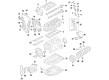
Volkswagen Golf R Camshaft Part Number: 06K-109-021
$293.37 MSRP: $400.79You Save: $107.42 (27%)Ships in 1-2 Business Days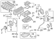
Volkswagen Golf R Camshaft Part Number: 06Q-109-022-D
$333.57 MSRP: $455.70You Save: $122.13 (27%)Ships in 1-2 Business Days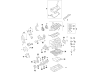
Volkswagen Golf R Camshaft Part Number: 06F-109-101-K
$533.74 MSRP: $729.15You Save: $195.41 (27%)Ships in 1-2 Business DaysVolkswagen Golf R Camshaft Part Number: 06K-109-022-R
$689.29 MSRP: $869.22You Save: $179.93 (21%)Ships in 1-2 Business Days
Volkswagen Golf R Camshaft
Choose OEM Camshaft for superior quality and long-lasting durability. They match the Volkswagen's factory specifications exactly and pass strict quality control. If you plan to replace Camshaft on your Golf R, put OEM at the top of your list. You'll get the right fit, reliable performance, and peace of mind. We stock an extensive inventory of genuine Volkswagen Golf R parts. It is easy to find what you need. You will love our competitive prices that help you save. No more hassle with returns or guesswork. Every part includes a warranty straight from the manufacturer. Get trusted quality, strong durability, and real value today.
Volkswagen Golf R Camshaft Parts and Q&A
- Q: What precautions should be taken when disconnecting the battery and performing camshaft and rocker arm repairs for 5-cylinder engines on Volkswagen Golf R?A:When the battery is disconnected, a number of systems will not work up until they are re-learned again. Otherwise, severe engine damage will be experienced in case of errors and therefore cannot be carried out by just anybody unless extremely experienced in such kind of work. In case of doubts about skills, refer to a professional. Check everything and verify that everything is in order before trying to start the engine. It is important to ensure that the camshafts and lifters are fully checked before the installation, and the check of camshaft endplay also before removal. Install the camshafts in timing adjust position, and then remove the camshaft sprocket and Timing Chain keeping the lobes and slots aligned with the camshafts as they were before removal. There are no individual camshaft bearing caps on this engine, as all the caps are assembled into a camshaft guide frame system. Relaxation of the camshaft guide frame bolts should be done half turn at a time until the pressure in the valve springs is relieved. New guide frame bolts are necessary, since old bolts are stretch-type fasteners that cannot give the correct readings of torque once they were used. Take out the guide frame, the camshafts and any remaining remnants of gasket material that is applied on matching surfaces and never reassemble them without conducting a careful inspection to ensure that they are in perfect condition. Inspect the camshaft bearing surfaces visually and in case damaged, the guide frame and cylinder head have to be changed. Take the measurement, both in terms of width, of the outside diameter of each camshaft bearing journal and also the inside diameter of each of the respective camshaft bearings. New camshafts, lifters, or/and guide frame and cylinder head could be needed in case overly worn. In order to measure the runout of the camshaft, the camshaft should be reinserted into the cylinder head and a dial indicator placed on the center journal that measures the readings and compares them with the recommended runout. In case the runout measured is beyond the specification, then change the camshaft. Install the cylinder head cover/guide frame temporarily and measure the endplay of the camshaft with a dial indicator; in case exceeds recommended values, inspect the guide frame under investigation. Determine lobe height of camshafts by means of a micrometer, comparing intake lobes to each other and exhaust lobes to each other; within a tolerance of more than 0.005 inch, change the camshaft. Check wear and scratches on contact and sliding surfaces of every lash adjuster and roller roller of every rocker arm, and make sure lash adjusters move freely in their bores. Apply oil on the lash adjusters and roller rocker arms and then fit them in the actual places. Clean and lubricate guide frame bearing surfaces and camshafts, you have to insert the camshafts in the guide frame with the recesses facing each other. Make sure that the sealing rings of the intake camshaft are uphill or downhill to avoid leakage of oil. Then with the help, carefully roll the guide frame and ensure that the camshafts do not drop out, making sure that the thread holes are aligned and the camshaft holding tool is installed and tightened to 15 ft-lbs (20 Nm). Using 1/8 inch of RTV sealant, apply the sealant around the edges of the guide frame and the spark plug holes, and then fit the guide frame assembly to the cylinder head. Install new bolts to the guide frames and tighten them in the correct order wiping off any surplus sealant. Cure sealant according to the recommendations by the sealant manufacturer and then add oil. Insert the sealing plugs at the end of the cylinder head and the guide frame of the camshaft until they are flush. It should be left to rest with the engine not rotated at all within 30 minutes. Turn the valve timing, and take out the camshaft holding tool and crankshaft locking pin. Before turning the starter switch on, turn the crankshaft by hand at least two full revolutions; any resistance met with should cause one to halt and investigate the situation. Refill the cooling system, and the rest of the installation is the reverse of the first one, being to see that the TDC marks again coincide when the engine has been rotated 2 full revolutions.
Related Volkswagen Golf R Parts
 Volkswagen Golf R Cam Gear
 Volkswagen Golf R Coil Springs
 Volkswagen Golf R Coolant Pipe Seal
 Volkswagen Golf R CV Joint
 Volkswagen Golf R Differential
 Volkswagen Golf R Door Lock Cylinder
 Volkswagen Golf R Exhaust Nut
 Volkswagen Golf R Fuel Cap
 Volkswagen Golf R Fuel Tank Strap
 Volkswagen Golf R Intercooler Hose
 Volkswagen Golf R Tail Pipe
 Volkswagen Golf R Valve Lifter