×
- Hello
- Login or Register
- Quick Links
- Live Chat
- Track Order
- Parts Availability
- RMA
- Help Center
- Contact Us
- Shop for
- Volkswagen Parts
My Garage
My Account
Cart
Genuine Volkswagen Golf R Cylinder Head
Head- Select Vehicle by Model
- Select Vehicle by VIN
Select Vehicle by Model
orMake
Model
Year
Select Vehicle by VIN
For the most accurate results, select vehicle by your VIN (Vehicle Identification Number).
3 Cylinder Heads found

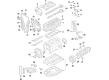
Volkswagen Golf R Cylinder Head Part Number: 06K-103-063-AP
$1199.26 MSRP: $1404.28You Save: $205.02 (15%)Ships in 1-2 Business DaysVolkswagen Golf R Cylinder Head Part Number: 06K-103-264-X
$1384.69 MSRP: $1621.41You Save: $236.72 (15%)Ships in 1-2 Business Days
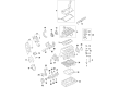
Volkswagen Golf R Cylinder Head Part Number: 06F-103-351
$3537.99 MSRP: $4142.84You Save: $604.85 (15%)Ships in 1-2 Business Days
Volkswagen Golf R Cylinder Head
Choose OEM Cylinder Head for superior quality and long-lasting durability. They match the Volkswagen's factory specifications exactly and pass strict quality control. If you plan to replace Cylinder Head on your Golf R, put OEM at the top of your list. You'll get the right fit, reliable performance, and peace of mind. We stock an extensive inventory of genuine Volkswagen Golf R parts. It is easy to find what you need. You will love our competitive prices that help you save. No more hassle with returns or guesswork. Every part includes a warranty straight from the manufacturer. Get trusted quality, strong durability, and real value today.
Volkswagen Golf R Cylinder Head Parts and Q&A
- Q: What precautions should be taken regarding the Cylinder Head when disconnecting the battery and performing engine work for 4-cylinder engines on Volkswagen Golf R?A:When the battery is not connected, one needs to re-learn several systems before they can work properly. This procedure can lead to the setting of a trouble code that must be cleared by a scan tool. Ease the fuel pressure, and remove the cable of the negative terminal of the battery. Unscrew the bolts of the right front wheel, lift up the front part of the vehicle and place it on jackstands. Block the other end of the wheels and take out the right front wheel. To do that, work under the vehicle, and then remove the lower splash guard under the engine, then on the engine compartment, the engine cover. Take out the drivebelts and the right front inner front fender liner. Run out the engine coolant and position engine TDC. In timing belt engines, the intake manifold must be removed and the engine supported at the bottom and passenger side mount removed then the Engine Mount support bracket bolt. Take out the timing belt and unscrew the electrical connections of the engine coolant temperature sensor, reduced oil pressure switch, fuel pressure sensor and fuel injector electrical connections. Take off the coolant housing fasteners and housing of the cylinder head, unscrew the exhaust pipe of the exhaust manifold of the 2.0L models, and unscrew the exhaust manifold/turbocharger of the 1.4L models. Take off the valve cover on 2.0L models and the camshaft housing on 1.4L models then take off the front exhaust pipe/catalytic converter then mark the point where the clamp will be installed. On 1.4L versions drop the right driveaxle heat shield bolts, heat shield and the oil pressure switch heat shield and oil pressure switch. Take off the intercooler lower connector pipe with fasteners and the lower connector pipe, plugging the lines, disconnect all electrical connectors of the turbocharger and remove oil supply and coolant supply banjo bolts. Disconnect the return line to the turbocharger and remove the turbocharger support bracket with fasteners and the support bracket that has the fasteners clinging to it. Take out the coolant reservoir, clamp the coolant hoses out on the end of the cylinder head, unplug and disconnect the coolant hoses to the coolant tube and pull off the coolant tube retaining fastener out of the heat shield. On 2.0L, loosen one upper bolt and the rear timing belt guard, and then loosen the fasteners of the electrical harness and loosen the harness at the end of the cylinder head. Installation Working in reverse of the order, loosen the bolts of the cylinder head in increasing amounts, until the bolts can be loosened by hand, and the previously used bolts are removed in order to put new ones attached during the re-installation. Ensure that nothing is attached to the cylinder head, then move the head off the cylinder block and with help where possible, take care and pry the cylinder head upwards in case of resistance. Take the gasket off the top of the block and keep it to identify it, and take the cylinder head to an engine machine shop prior to reinstallation. The mating surfaces of the cylinder head and cylinder block should also be scrupulously clean prior to receiving the head; a scraper made of hard plastic or a piece of wood should be used to rub off all the carbon and gasket remnants so that no carbon gets into the oil and water passages. Inspect mating surfaces of nicks and scratches and in case of evidence of warpage, check by using a straight-edge. Clean up the holes of the cylinder head bolts with an appropriate tap, and make sure that they are clean and dry before the head bolts are fitted. Adjust the crankshaft to TDC in cylinder No. 1 and turn back slightly. Install the new head gasket in the cylinder block, making sure that the dowel pin in the gasket is making contact with the dowel pins in the cylinder block. Be sure that the manufacturer markings are facing up. Use some help to hold the cylinder head in the middle of the cylinder block and make sure that the dowel pins are fitting in the holes of the cylinder head and verify the proper fitting of the head gasket. Install the bolts that hold the cylinder head in place and screw them in by hand since the old ones are of the stretch type. Secure the cylinder head bolts in phases to the torque and the angle of rotation by use of an angle-measuring gauge to ascertain the correctness. Turn the crankshaft clockwise by a step or so to position the engine back at TDC, making sure that the mark on the crankshaft pulley is aligning to the mark on the front cover. Install camshaft housing on 1.4L model, and then attach the intake manifold, fuel rails, timing belt tensioner and camshaft sprocket (where removed). Install and believe the timing belt and rotate the crankshaft by hand with at least two complete rotations ensuring resistance. The rest of the installation procedure is the opposite to the removal process, which is then followed by filling the engine oil and filter, the cooling system and running the engine to check on any leakage. In the case with Timing Chain engines, detach top timing chain cover, air charge pipe with fasteners, and charge air cooler lower connector pipe with fasteners. At the bottom of the engine, support the engine and take out the engine mount of the passenger side after which take out the timing chain and camshafts. Undress the hoses on top of the cylinder head, disconnect the front exhaust pipe/catalytic converter, and disconnect the electrical connectors on the reduced oil pressure switch and oil pressure switch. Disassemble intake manifold, loosen intake manifold support bracket fasteners and bracket, and disconnect all electrical connector to the intake manifold and throttle body, and take away exhaust manifold heat shield. Unplug all electrical connectors of the turbocharger and unplug it, unplug the vacuum hose of the pump of CBFA and CCTA models. Disconnect electrical connectors on the hose of the crankcase ventilation system, the housing (where applicable), and disattach the hose of the secondary air injection system and the hose to the intake manifold. In the case of CBFA and CCTA models, a special tool should be inserted in the control valve and rotated clockwise then removed. Manually turn the engine until the No. 1 cylinder reaches TDC and align the camshaft timing chain with camshaft sprockets. Disassembly. Take out the tensioner access hole plug, squeeze the Timing Chain Tensioner and take out the timing chain off the camshaft sprockets. Do not turn the engine after the removal of the timing chain. Take out the ignition coils and unhook the electrical connector of the camshaft position sensor. Unscrew the bolts that hold the cylinder head and remove the smaller bolts in the front of the cylinder head first and then remove the bolts that hold the cylinder head in an inverted order. Use great caution when removing the cylinder head assembly as not to damage the timing chain guide rails and place it on two blocks of wood and then remove the intake manifold. Position the new head gasket on the cylinder block and position the crankshaft on TDC on No. 1 cylinder and place the dowel pins into the new head gasket. Insert the cylinder head centrally on the block of the cylinder with the help of an aid and make sure that the dowel pins are inserted into the recesses in the cylinder head. Install the bolts, which are to be hand-tightened, on the cylinder head using new bolts. Install the cylinder head bolts step-by-step to the amount of torque and the angle of rotation with precision. Turn the crankshaft to TDC and align the crankshaft pulley with the mark on the timing chain cover and slide the timing chain across the camshaft sprocker and align it with the marks made before TDC. Install the camshaft upper guide, and take the pin that holds the tensioner in the compressed position and with care turn the crankshaft by hand at least two full revolutions making sure there is no resistance. The rest of the installation process is the reverse of the removal process, then the engine oil and filter change, followed by filling up the cooling system, and then running the engine to check it to ensure there are no leaks.

Related Volkswagen Golf R Parts
 Volkswagen Golf R Axle Beam Mount
 Volkswagen Golf R Axle Support Bushings
 Volkswagen Golf R Belt Tensioner Bolt
 Volkswagen Golf R Cooling Fan Assembly
 Volkswagen Golf R Differential
 Volkswagen Golf R Exhaust Clamp
 Volkswagen Golf R Exhaust Manifold Gasket
 Volkswagen Golf R Fuel Cap
 Volkswagen Golf R Shock And Strut Mount
 Volkswagen Golf R Stub Axle
 Volkswagen Golf R Throttle Body Mounting Gasket