×
- Hello
- Login or Register
- Quick Links
- Live Chat
- Track Order
- Parts Availability
- RMA
- Help Center
- Contact Us
- Shop for
- Volkswagen Parts
My Garage
My Account
Cart
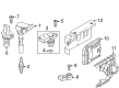
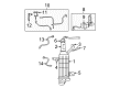
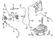
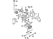
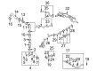
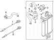
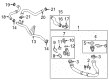
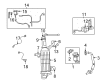
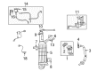
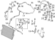
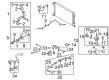
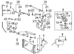
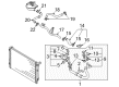
Genuine Volkswagen Oxygen Sensor
Oxygen O2 Sensor- Select Vehicle by Model
- Select Vehicle by VIN
Select Vehicle by Model
orMake
Model
Year
Select Vehicle by VIN
For the most accurate results, select vehicle by your VIN (Vehicle Identification Number).
92 Oxygen Sensors found


Volkswagen Oxygen Sensor Part Number: 03H-906-262-AP
$163.99 MSRP: $229.68You Save: $65.69 (29%)Ships in 1-2 Business DaysProduct Specifications- Other Name: Front Oxygen Sensor
- Position: Passenger Side


Volkswagen Oxygen Sensor Part Number: 7B0-906-265-A
$68.48 MSRP: $95.92You Save: $27.44 (29%)Ships in 1-2 Business DaysProduct Specifications- Other Name: Lower Oxygen Sensor
- Position: Passenger Side


Volkswagen Upper Oxygen Sensor Part Number: 06K-906-262-P
$117.02 MSRP: $163.90You Save: $46.88 (29%)Ships in 1-2 Business DaysProduct Specifications- Other Name: Oxygen Sensor
- Position: Upper


Volkswagen Oxygen Sensor Part Number: 021-906-265-AH
$143.51 MSRP: $201.00You Save: $57.49 (29%)
Volkswagen Oxygen Sensor Part Number: 021-906-265-AL
$147.14 MSRP: $206.08You Save: $58.94 (29%)


Volkswagen Oxygen Sensor Part Number: 022-906-262-CC
$154.70 MSRP: $216.67You Save: $61.97 (29%)Ships in 1-2 Business DaysProduct Specifications- Other Name: Rear Oxygen Sensor
- Position: Passenger Side

Volkswagen Rear Oxygen Sensor Part Number: 06K-906-262-EA
$10.53 MSRP: $17.26You Save: $6.73 (39%)Ships in 1-2 Business DaysProduct Specifications- Other Name: Oxygen Sensor
- Position: Rear

Volkswagen Oxygen Sensor Part Number: 06K-906-262-AP
$97.34 MSRP: $136.30You Save: $38.96 (29%)Ships in 1-2 Business DaysProduct Specifications- Other Name: Rear Oxygen Sensor

Volkswagen Oxygen Sensor Part Number: 7B0-906-265
$67.16 MSRP: $94.07You Save: $26.91 (29%)Ships in 1-2 Business DaysProduct Specifications- Other Name: Rear Oxygen Sensor
Volkswagen Oxygen Sensor Part Number: 06K-906-262-BF
$69.29 MSRP: $97.05You Save: $27.76 (29%)Ships in 1-2 Business DaysProduct Specifications- Other Name: Rear Oxygen Sensor

Volkswagen Oxygen Sensor Part Number: 7B0-906-262-A
$145.17 MSRP: $203.32You Save: $58.15 (29%)Ships in 1-2 Business DaysProduct Specifications- Other Name: Front Oxygen Sensor, Rear Oxygen Sensor

Volkswagen Oxygen Sensor Part Number: 7B0-906-262-B
$145.17 MSRP: $203.32You Save: $58.15 (29%)Ships in 1-2 Business DaysProduct Specifications- Other Name: Lower Oxygen Sensor, Upper Oxygen Sensor

Volkswagen Oxygen Sensor Part Number: 06E-906-262-K
$145.76 MSRP: $204.15You Save: $58.39 (29%)Ships in 1-2 Business DaysProduct Specifications- Other Name: Front Oxygen Sensor
- Position: Passenger Side

Volkswagen Oxygen Sensor Part Number: 06A-906-262-BG
$145.17 MSRP: $203.32You Save: $58.15 (29%)Ships in 1-2 Business DaysProduct Specifications- Other Name: Rear Oxygen Sensor

Volkswagen Oxygen Sensor Part Number: 1K0-998-262-AE
$148.74 MSRP: $208.32You Save: $59.58 (29%)Ships in 1-2 Business DaysProduct Specifications- Other Name: Oxygen Sensor Kit
- Replaces: 03G-906-262, 03L-906-262-C, 06A-906-262-DE, 07Z-906-262-G, 07Z-906-262-E, 07Z-906-262-F, 07Z-906-262-D

Volkswagen Oxygen Sensor Part Number: 06K-906-262-CF
$155.88 MSRP: $218.32You Save: $62.44 (29%)Ships in 1-2 Business DaysProduct Specifications- Other Name: Lower Oxygen Sensor, Rear Oxygen Sensor
- Replaces: 06K-906-262-BA
Volkswagen Oxygen Sensor Part Number: 06E-906-262-L
$177.30 MSRP: $248.32You Save: $71.02 (29%)Ships in 1-2 Business DaysProduct Specifications- Other Name: Front Oxygen Sensor
- Position: Driver Side

Volkswagen Oxygen Sensor Part Number: 051-906-265-E
$154.44 MSRP: $216.30You Save: $61.86 (29%)
Volkswagen Oxygen Sensor Part Number: 7B0-906-262
$155.47 MSRP: $217.75You Save: $62.28 (29%)Ships in 1-2 Business DaysProduct Specifications- Other Name: Front Oxygen Sensor

Volkswagen Oxygen Sensor Part Number: 078-906-265-F
$157.08 MSRP: $220.00You Save: $62.92 (29%)Product Specifications- Position: Driver Side
| Page 1 of 5 |Next >
1-20 of 92 Results
Volkswagen Oxygen Sensor
The Volkswagen Oxygen Sensor continuously monitors the oxygen levels in the exhaust stream, allows the engine computer to fine-tune fuel flow and in turn provides strong performance in low emissions. Founded in 1937 with the vision of a reliable people car, VW went from the iconic Beetle and adaptable Type 2 van to a full range of cars that combine clean design with rock-solid engineering. Today VW uses TSI turbo engines and direct fuel injection as well as the versatile MQB platform to reduce weight and costs, and features such as the digital cockpit, park assist, and touchscreen MIB infotainment give the car modern convenience. The brand also pushes into electric mobility with the ID.3 and ID.4, proving VW is still devoted to innovation and sustainability for drivers around the world. Just like the evolution of the brand, the Oxygen Sensor also undergoes an evolution process, sitting in the exhaust stream of gasoline or hybrid vehicles, quickly generating signals between rich and lean mixtures. Its heated zirconia element reaches operating temperature within minutes, with the control unit being able to adjust injectors for cleaner combustion and improved mileage across the entire range. A healthy sensor helps to maintain the efficiency of the catalytic converter, prevent engine hesitation, and save fuel, so periodic replacement ensures performance for any model from compact hatchbacks to roomy SUVs.
Buying OEM parts is a smart move to keep your long-term repair costs low. These components are built to last because VW uses such strict factory standards. At VWPartsGiant.com, it is easy to find genuine Volkswagen Oxygen Sensor at prices that actually beat the competition. You get a real manufacturer's warranty with every single part, so you know your purchase is safe. Plus, forget about return headaches since our policy is easy and worry-free. We ship your order fast, too. If you have questions, our team of parts experts is ready to help. Why wait? Start shopping now!
Volkswagen Oxygen Sensor Parts and Q&A
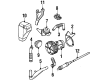
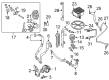
- Q: How to properly service and remove an oxygen sensor without causing damage on Volkswagen Jetta?A:Since the oxygen sensor is fitted in the exhaust pipe, which is contracting when cold, it might be hard to loosen when the engine is cold. To prevent breaking an oxygen sensor or damaging its threads, ensure that you turn on and run the engine a minute or two then turn the engine off without burning yourself in the process. Particular care should be taken when servicing an oxygen sensor because they can never be taken apart by a permanent pigtail and have an electrical connector which cannot be removed; they would be permanently damaged. Also, do not allow grease, dirt and any other contaminants to touch the electrical connector and the louvered end of the sensor and never use any cleaning solvents on the connector. Oxygen sensors are very sensitive and therefore they should not be dropped or mishandled and the silicone boot should be fitted properly to avoid melting. Removing an upstream oxygen sensor: Find the oxygen sensor at the upper end of the catalytic converter or at the end of the exhaust manifold of 2.5L engines, and locate the wiring harness and strip the electrical connector of the sensor harness disengaging it. Unscrew sensor with an oxygen sensor socket to use on tight areas, and in case of re-insertion of the old sensor, apply anti-seize to the threads, which new sensors are already coated. In the case of downstream sensors, place the sensor in the centre and following the catalyst, disconnect the electrical connector, unscrew the sensor and place anti-seize compound in the case of replacing the old sensor. Installation is the opposite of removal and it is imperative to ensure that the oxygen sensor is firmly screwed to the required torque.
- Q: What are the differences in oxygen sensor configurations, and how do they function in relation to the ECM and air/fuel ratio on Volkswagen Passat?A:The four-cylinder models are fitted with two oxygen sensors, each pre-converter and post-converter, V6 models fitted with four each. The sensor elements interact with the oxygen in the exhaust to produce varying voltage output to a lean mixture of 0.1 volt to a rich mixture of 0.9 volt. The pre-converter sensor, which occurs in the front of the catalytic converter, provides feedback to the ECM about the oxygen concentration in the exhaust and thus it allows it to regulate the pulse width of the fuel injector and keep the air/fuel ratio at an optimal level at 14.7:1, resulting in optimal emissions, fuel economy and performance. The post-converter sensor, which follows the catalytic converter, has no effect on the air/fuel ratio, but assists the ECM in detecting efficiency of the catalytic converter by generating a slower changing voltage signal. The oxygen sensor does not produce a voltage until it reaches around 600-degrees F when the ECM will switch to an open-loop fuel control mode and depend upon other sensor inputs instead. The correct functioning of sensors needs proper electrical connections, free air circulation, right operating temperature, and usage of unleaded fuel. The ECM is able to detect different oxygen sensor faults and program diagnostic trouble codes and revert to open-loop control when defects arise. It is recommended to warm the engine a little to ease the removal of sensors and to take caution not to get burnt. In changing a sensor, the permanently attached pigtail and electrical connector are to be left in place and contaminants should be avoided in the connector and sensor end. The solvents are not to be cleaned and the sensor must be handled delicately. To replace the sensor which is of the pre-converter type, an opening is first achieved by removing the required parts, and to replace the sensor that is of the post-converting type, the vehicle should be placed safely on jackstands. Electrical connector is to be disconnected, and the sensor could be disassembled with the help of appropriate wrench or special socket. To ensure that the sensor threads could later be removed easily, one should apply an anti-seize compound to the thread, and then the sensor should be installed and firmly tightened after which the electrical connector has to be reconnected and the removal procedure should be followed in reverse.


Related Volkswagen Parts
 Volkswagen Coil Springs
 Volkswagen Ignition Lock Cylinder
 Volkswagen Air Intake Hose
 Volkswagen Axle Support Bushings
 Volkswagen Brake Shoe Set
 Volkswagen Catalytic Converter Gasket
 Volkswagen Coil Spring Insulator
 Volkswagen Distributor Rotor
 Volkswagen Fuel Filler Housing
 Volkswagen Intake Valve
 Volkswagen Intercooler Hose
 Volkswagen Shock Absorber
Browse by Model
Arteon Oxygen Sensor Atlas Cross Sport Oxygen Sensor Atlas Oxygen Sensor Beetle Oxygen Sensor Cabrio Oxygen Sensor Cabriolet Oxygen Sensor CC Oxygen Sensor Corrado Oxygen Sensor Eos Oxygen Sensor EuroVan Oxygen Sensor Fox Oxygen Sensor Golf Alltrack Oxygen Sensor Golf Oxygen Sensor Golf R Oxygen Sensor Golf SportWagen Oxygen Sensor GTI Oxygen Sensor Jetta Oxygen Sensor Passat Oxygen Sensor Phaeton Oxygen Sensor R32 Oxygen Sensor Rabbit Oxygen Sensor Routan Oxygen Sensor Taos Oxygen Sensor Tiguan Limited Oxygen Sensor Tiguan Oxygen Sensor Touareg Oxygen Sensor Vanagon Oxygen Sensor